Dry Braking

As easy as A.B.SSafety concerns have been driving the automotive sensor market towards newer and more effective technology. Anti-lock braking systems (ABS) can bring stability to your sales. The 1990s saw safety emerge as a major consideration and features such as traction control, stability control systems and anti-lock braking system (ABS) have been applied across a wide sector of the industry. Since 2012, the fitment of ABS as a standard has been mandated for all passenger cars and light vehicles. THE ABS PRINCIPLE ABS is a safety system that prevents wheel lock during braking. This enables the driver to maintain steering control and avoid uncontrolled skidding. ABS also provides improved vehicle control and decreased stopping distances on dry or slippery surfaces. However, ABS will not offer any benefits on ice/snow-covered roads as there isn’t enough traction between the tyre and the road. Not only does the modern ABS prevent wheel lock under braking, it may also electronically control the brake bias towards all brakes. This function, depending on its specific capabilities and implementation, is known as electronic brake force distribution (EBD). Other functions of the anti-lock braking system can include traction control, emergency brake assist and electronic stability control (ESC), depending on the system and manufacturer.
ABS SENSORS AND THEIR WORKING ABS uses a wheel speed sensor, commonly called an ABS sensor, to monitor the rotational speed of each wheel. These sensors send the information to an electronic brake control module (EBCM), which in turn controls the operation of the electrohydraulic unit that regulates the flow of brake fluid to each wheel brake. Although there are numerous variations of ABS sensors, they all fall into two categories: • Inductive ABS sensors (Passive) – when no additional power supply is required • Hall Effect ABS sensors (Active) – when a power supply is connected to the sensor
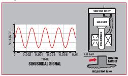
INDUCTIVE ABS SENSOR (PASSIVE) Essentially, the sensor comprises of a coil wrapped around a magnet. This sensor is positioned close to the ‘reluctor ring’ which consists of a toothed ring mounted on the wheel hub. Each time a tooth of the ring passes the sensor, a small electrical voltage is induced within the copper coil. This voltage is transmitted to the ECU in the form of a sinusoidal signal (or a sine wave) that is used to calculate the vehicle’s wheel speed.
This is a basic form of an ABS sensor and is susceptible to interference or false cycling from factors such as a corroded reluctor ring or debris on the sensor head. The inductive ABS sensor does not start working until the vehicle has achieved a speed of 3-5mph.
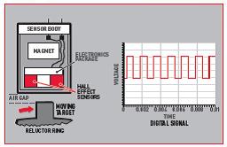
HALL EFFECT ABS SENSOR (ACTIVE) A Hall Effect sensor is an active sensor that uses the addition of a power supply to create a digital output. The power supply is connected to a Hall Effect element creating a consistent current flowing through it. When the element is subjected to a magnetic field of sufficient strength and polarity created by the passing reluctor ring, it deflects the current across the Hall-element creating an on/off voltage signal.
This type of sensor will start working straightaway and doesn’t suffer from false cycling. It is more sensitive and accurate than a passive sensor, allowing systems such as electronic stability programmes to be incorporated in modern ABS systems.
In both passive and active ABS sensors, a signal (either sinusoidal or digital) is transmitted to the ECU that uses the data to determine the wheel speed and evaluate whether the ABS should intercede to control braking. The vehicle is at its maximum stability when all the four tyres have traction and are spinning at the same rate. MALFUNCTIONING ABS SENSOR Wear and tear is the most common reason for an ABS sensor failure on any vehicle. The position of the sensor and constant movement of the vehicle’s steering and suspension make it vulnerable to detrimental factors such as: • heat from the brakes • vibrations • threat of dirt and moisture ingress Generally, a scan tool is used to diagnose an ABS sensor problem. A digital multi-meter or oscilloscope reads the pulse and accurately displays the ABS wave pattern. A code reader can be used to read trouble codes relevant with the specific fault. It is recommended that the vehicle should be driven a short distance following the replacement of a faulty sensor for the system to recognise the new part. Failure to do so may result in the fault code not clearing, giving the impression that the new part is faulty too.
|
Related Articles Related Downloads |