ABS Operation
Back to Video Library
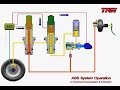
DescriptionThis short video demonstrates the hydraulic function of the ABS system. The main elements of the ABS system in the diagram are (from left to right): Wheel, with brake caliper and wheel speed sensor
Normal Braking: ABS Operation not Required Hydraulic pressure is generated by operating the brake pedal; as the ISO valve in the ABS control unit, which is normally open, has not been activated, there is a direct hydraulic connection to the wheel brake, which is therefore applied. The wheel has not, in this instance, been locked so the pressure can act without change within the brake cylinders; the DUMP valve is closed, and the non-return valve prevents fluid under pressure from passing to the LPA (low pressure accumulator). Braking proceeds in the normal way. Braking: ABS Operation Required Pressure maintenance phase It is assumed that braking has caused the wheel to start to lock; the sensor detects the sudden change in wheel speed, and the control unit acts to prevent any further increase in pressure at the brake. To do this, the ISO valve solenoid is triggered by the control unit, and the valve is closed, isolating the fluid in the pipe to the brake. Braking: ABS Operation Required Pressure reduction phase If the wheel is still tending to lock, despite the brake pressure being maintained at a constant level, the continuing signals from the sensor will cause the control unit to trigger the solenoid of the DUMP valve. The DUMP valve now opens, and some fluid from the brake now passes into the LPA (low pressure accumulator), reducing the pressure in the brake cylinders; the braking effort being reduced, the wheel can accelerate, reducing the amount of slip and improving the grip of the tyres on the road. At the same time, the ABS pump extracts the brake fluid out of the LPA (low pressure accumulator) via the first non return valve, and pumps it towards the ISO valve (which is still closed), via the second non- return valve. As there is a hydraulic connection to the master cylinder, and the pump delivery pressure is greater than the pressure from the master cylinder, more than sufficient to open the non return valve, the driver will notice a pulsation effect on the brake pedal. Once the wheel has ceased to lock, the brake pressure can be increased. The signal from the sensor will therefore cause the control unit to allow the DUMP valve to return to its normal (closed) position. To guarantee a smooth pressure build-up, the ISO valve is opened frequently. The master cylinder is again in communication with the brake cylinder. Normal Braking: ABS Operation not Required Hydraulic pressure is generated by operating the brake pedal; as the ISO valve in the ABS control unit, which is normally open, has not been activated, there is a direct hydraulic connection to the wheel brake, which is therefore applied. The wheel has not, in this instance, been locked so the pressure can act without change within the brake cylinders; the DUMP valve is closed, and the non-return valve prevents fluid under pressure from passing to the LPA (low pressure accumulator). Braking proceeds in the normal way. Please note, the above sequence takes place in a fraction of a second! |
Related Articles Related Videos Related Downloads |