Turbo

Turbo REA & SREA
The VNT (Variable Nozzle Turbine) turbocharger is designed to match the size of the turbine to suit the maximum rated power of the engine, without compromising on low speed response. Latest VNT models use full electronic control of the vanes for:
REA/SREA malfunction Movement of the vanes is controlled by the REA (Rotary Electronic Actuator) or SREA (Simple Rotary Electronic Actuator). Failure (or apparent failure) of the actuator is indicated by:
What should you do if you suspect a fault in the REA or SREA? 1. Ask the customer to fully describe the problem, including the exact conditions when the failure occurred:
2. Check the vehicle service history for past problems, previously recorded ECU error codes and replaced engine components, particularly concerning the EGR valve(s). 3. Check the vehicle records to see if the battery or alternator has been changed, or if the voltage has ever dropped low enough to prevent the engine cranking. Check the voltage now; if it is correct, the actuator should reset itself. 4. Plug in the diagnostics for the vehicle engine control unit (ECU) and record all failure codes, and their frequency. 5. With the engine immobilised and cold, check if you can see or feel the linkage between the REA/SREA and the turbo. If it’s accessible, check it’s not detached at either end. Test the linkage to check that there’s a small amount of play at each end. If there is not any play, check for corrosion at each end of the linkage; this may be restricting movement. Remove and check that the vane assembly operating lever is free. If the linkage is tight, move the crank assembly by hand a few times. If it frees up, reconnect the linkage and test again. If the crank assembly is very tight or won’t move at all, contact BTN Turbo for further advice. Do not apply leverage as this may cause further damage. The turbo will need to be removed to diagnose the reason for restricted vane movement. 6. Check the REA/SREA electrical connector is firmly located. Press both end tabs, pull it off and check for damage. Check for water or staining below the connector seal and in the REA/SREA connector well. Check the REA/SREA connector walls for damage or cracks. While the plug is disconnected, inspect all the individual wires on the vehicle wiring loom for damage or breaks. Reconnect, ensuring the location tabs click into place securely.
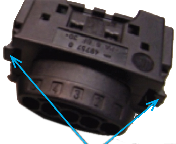
Location tabs: squeeze inwards to remove connector.
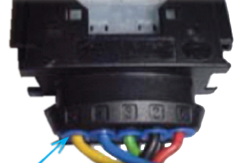
Gently pull on each harness wire in turn to check it’s firmly located within the connector. Check each wire is sealed as it enters the connector; if there are less than five wires, the unused positions should be fitted with a sealing plug.
Waterproof seals around the wires.
7. Switch on the ignition without cranking the engine and check the warning lights status, including the glow plug if applicable. You should see or hear the REA move to the minimum vane open position. Start the engine and watch or listen again for the REA movement. Check again if any warning lights are on, indicating a possible electrical fault. Switch the ignition off. The REA should move rapidly to the open vanes position, often with a high-pitched noise. On some applications, the REA may do this two or three times during the shutdown cycle after the engine has stopped. This is to clean the vane path. If all tests up to step 7 are passed, stop at this point and diagnose the vehicle systems – it is unlikely there is a fault with the electronic actuator. Remember:
|
Related Articles Related Downloads |

