Switches & Sensors

Air Mass Sensor TroubleshootingSporadic Faults
Above right: Oil misted air mass sensor Therefore, if the OBD shows a sporadic fault on the air mass sensor it may not necessarily be defective. Often the measuring results are falsified by moisture, oil mist or dirt and this is interpreted by the OBD as a fault. The causes described above may be the reasons for these sporadic faults. Consequently, an inspection of the incorporated air mass sensor should always be carried out prior to installing a new air mass sensor. Sensor Testing On conventional air mass sensors, the output signal can be measured as an analogue voltage with the aid of any commercial multimeter. Details concerning the inspection of these air mass sensors are available in Pierburg Service Information SI 0017/A and SI 0079, which can be found in the 'Service Information' section under 'Pierburg'. On air mass sensors of the more recent generation this is no longer possible, as the data is transferred by a digital pulse width modulation (PWM) signal. These new air mass sensors may also incorporate an intake air temperature sensor, the measuring values of which are transferred by the same PWM signal. A control current is needed in order to actuate the latest Pierburg air mass sensors by means of the engine control unit. This is however, not a direct current but a current that is pulsed at a certain frequency ("pulse width modulation" or "PWM"). With air mass sensors of the more recent generation, an oscilloscope can be used to make a qualitative statement on the condition of the sensor, before the customer/fitter has to worry about purchasing a replacement unit.
The diagram to the left demonstrates the output from an oscilloscope test - when the accelerator pedal is pressed, the frequency should change with the increasing air mass flow. The "on-duration" of one pulse, as illustrated by the green arrow, is referred to as the "pulse duty factor". Important maintenance tip: when inspecting and testing air mass sensors, never use compressed-air to blow out the unit – this could destroy the sensor!!! Summary In summary, air mass sensors are vital components in the engine management system - if they are not functioning correctly, then other components will not function correctly either and the OBD system is likely to register engine management faults. Air mass sensors can be subjected to harsh conditions and may suffer from oil misting or salt spray (amongst other contaminants) and therefore should be carefully checked when exploring engine management faults. In addition to this, it is vital that the vehicle technician/mechanic identifies the root cause of any contamination or damage that has occured.
|
Related Articles Related Downloads |
 Impurities or oil on an air mass sensor can cause so called "sporadic faults", i.e. the malfunction indicator lamp suddenly lights up, and then goes out after a period of time. At this point it is necessary to explain something about the working principle of the OBD: not every fault detected by the OBD results in the malfunction indicator lamp lighting up immediately. Any fault affecting the exhaust gas is detected during a driving cycle, even though the malfunction indicator lamp does not light up. The malfunction indicator lamp is only activated if the same fault re-occurs during the next driving cycles or during a defined period. The malfunction indicator lamp can also go out if a fault does not appear again during a defined period.
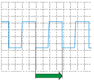
| Previous page |